Low Voltage Power Supply Project
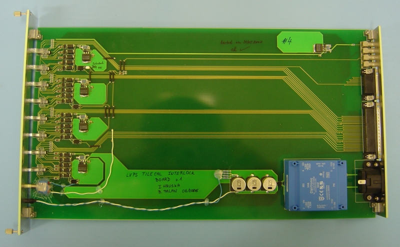
DSS-LVPS Interlock Board
The LVPS interlock board is receiving the ATLAS-DSS (Detector Safety System) cooling interlock
signals. In case of interrupted water cooling to the Tile Calorimeter, one LVPS
Interlock Board will disable functioning of 64 LVBOXes. It is also hardwired together
with 16 channels of 200VDC HPS1 bulk power supplies and 16 AUX Boards. Four DSS-LVPS
Interlock pcb boards are needed to stop/control 256 finger LVBOXes, they are
installed in the USA15 control room.
Additional 16ch (+1ch spare) Isource
Board has been designed in order to fully equip interlock current loops between
16 HVS1 power supplies and four DSS-LVPS Interlock Boards. This Isource board
provide 16 independent dc current of 15mA.


● DSS-LVPS
Interlock v.1 production version
► Design files
● Scheme v.1 final (Ulticap 5.72
Ultimate)
UTSCH file
● Scheme
v.1 final
PDF(A4 format)
● PCB design file (Ultiboard 5.71
Ultimate)
ddf file
note: attention to optocouplers pinout, original file, post pcb
modifications
● PCB Component
placement
PDF(A3 format)
note: attention to optocouplers pinout, original file, post pcb
modifications
● Bill of
Material final
EXCEL
► Process & pcb manufacturing file (CAM350
format)
Zip
► Front panel & back panel
mechanics PDF_1
, PDF_2
► DSS-LVPS
Interlock Board Photos
► PIT Interconnection Scheme Manual (Jacob Jan2008)
PDF
note: interconnection for 1/4 partition = 16 LVBOXes, 4 AUX, one HVS1
first scheme without final 16ch Isource Board connecting HVS1
Final Installation Scheme (Jacob March 2008)
PDF soon
☞
Service Manual
design files and interconnection manual can be used
● Subsidiary 16ch+1ch spare Isource Board for 16 HVS1 and 4 DSS-LVPS
Interlock Boards
► Design files – Inst of Physics Prague
(schemes, comp. placement, and comp. list, manufacturing file etc.)
ask IOP
Preliminary schemes (in czech)
PDF_1,
PDF_2
► Front panel & back panel
mechanics PHOTOS


