

Low Voltage Power Supply Project
LVBOX StartUp Tool without AUX Board
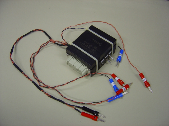
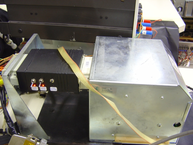
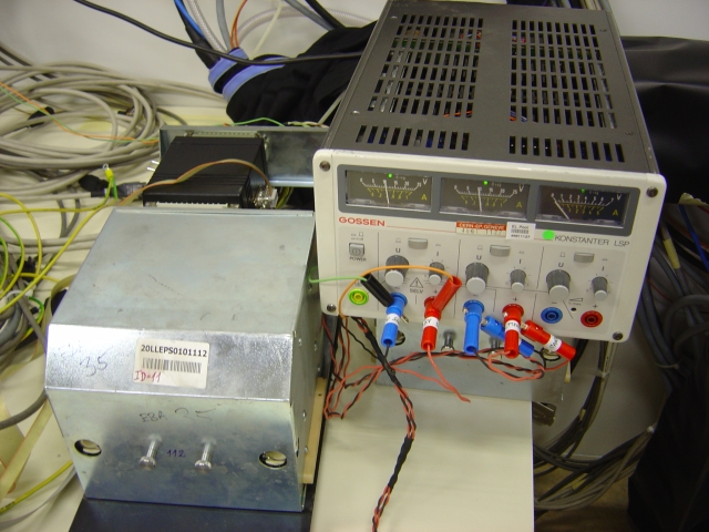
This simple extension tool can be used when connected between the LVBOX and a TileCal drawer (LVBOX dummy loads). In order to start the LVBOX we don't need an AUX (auxiliary) board. The LVBOX needs three external power supplies: +200Vdc to power dc/dc converters, +10Vdc to power the ELMB chip and ELMB_MB together, and a StartUp pulse of +10 - 15Vdc for 1second. The Startup tool enables to connect CsAN bus for trimming Vout of bricks to minimum and later to nominal values. If no CANbus interface is applied, the LVBOX starts at maximum Vout.
Required Power supplies:
► Scheme of the LVBOX StartUp Tool v.3 (June 2008) PDF
Procedure to use the LVBOX StartUp tool:
1. Connect the tool between HARTING_M of the LVBOX and a drawer HARTING_F connector (LVBOX dummy load) 2. Apply +10Vdc to the ELMB+MB power, connect +15Vdc StartUp, connect +200Vdc PS 3. a) If not using CANbus skip the following b) If using CANbus communication, apply +10Vdc to power CAN, verify the length, use 120 ohm terminator. Using Winhost+ program: - check the ELMB chip is responding, verify ID of the LVBOX/ELMB - using SDO commands in Winhost+ set DAC values (MAX525) to start all bricks at Vout minimumSet MAX525 chip to start at minimum
SDO commands in Winhost+ program:
Node ID == ELMB address (switch)
OD index == 6411 (data size 16-bit)
Data == FFFF (minimum output
voltage =4095)
repeat for
OD sub index == 1 to 4 and 11 to 14 to set all the brick
according to the following map:
1 Dig +5
2 HV +5
3 Dig +3
4 HV -15
11 MB +5
12 MB +15
13 HV +15
14 MB -5
(the same can be done to set the voltage level )